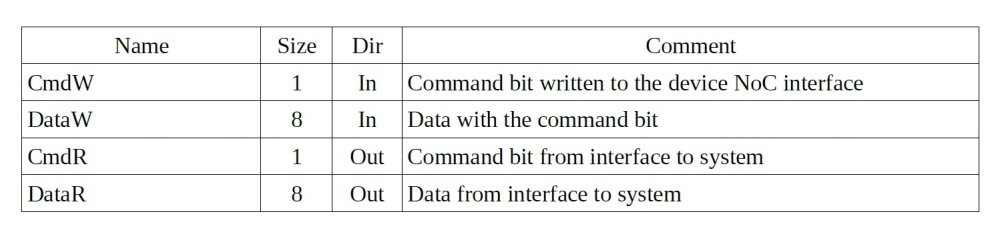
This project makes a pair of low pin count uni directional bus. It enables the CRC generator to read and write data to memory. The interface of the bus is the following:
This network on chip works on 8-bit custom bus protocol. It supports 8 basic packets for transmission. The first bit in the packet is the control bit. It indicates a framing byte. If set, then the packet is a command. If cleared, then the packet is meant to be ID or data. For example, the read command is used to start a read operation. During the first byte, the control bit will be set, indicating a command. However, it will be cleared for the following bytes, when SourceID and address are sent over the bus.
Salient Points:
- When a read command is sent by a bus master, the slave must send a read response.
- Read Command has AddrLen(length of address), Ones(default values of address bits not sent), Len(Size of length field→’0′ means 1 byte and ‘1’ means 2 bytes).
- The order of bytes is as follows: Read Command → SourceID → Address → Read length.
- Read Response has control bit set as ‘1’.
- Following the control byte of Read Response, the slave must send the Return ID. Source ID should match the Return ID. They are meant to ensure that all masters receive the correct packet.
- The End command is used only to terminate a Read Response. They are ignored in any position.
- Write Command is same as read command. The write data is sent after the length field. Write Command → SourceID → Address → Length → Write Data.
- The scope of this project does not cover the use of SourceID and ReturnID.
